Contents
Overview
This is the third article in a series that explores GPIO programming on a Raspberry Pi 3B+. The first is Raspberry Pi GPIO in Go and C - Blinking LED. It is a supplement to the Sunfounder RGB LED project. You can find the full series here.
This article explores the use of Pulse Width Modulation (PWM) to drive an RGB LED, as well as how to control an individual LED pin’s brightness. The code samples will be in Go and C.
Prerequisites
If you don’t have one, you’ll need a Raspberry Pi. I used a Raspberry Pi 3B+ with the ‘stretch’ version of the Raspbian OS. Given that the Sunfounder Ultimate Starter Kit is advertised to work with a Raspberry Pi 4, I would expect the 4 series to work as well. I’m less sure about other Raspberry Pi versions, especially versions with 26 vs. 40 GPIO pins.
Next you’ll need
You should also consider getting a 40 pin female to female with a T-Type adapter to attach the GPIO outputs to the breadboard. You can use only jumper wires, but the cable will make things easier and will help prevent damage to the GPIO pins on the Raspberry Pi. If you elect not to buy the 40 pin cable with T-Type adapter you’ll need to buy male-to-female jumper wires. Buying all these things separately will cost more than a kit however. Here’s a simple kit that has all of the above. If you expect to follow this series I recommend buying the Sunfounder Raspberry Pi Ultimate Starter Kit.
You will also need some basic C and Go programming knowledge as well as familiarity with logging on to a Raspberry Pi terminal, or into the desktop GUI that comes with some OS versions. Depending on the approach you take, you may need to connect a keyboard and monitor to the Raspberry Pi. I simply SSH into the Pi. You’ll also need familiarity with how to use an editor like Vi or nano.
To compile and run the C program you’ll need the WiringPi1 libary. It’s easy to get:
sudo apt-get install wiringpi
Then test the installation using:
pi@pi-node1:~/go/src/github.com/youngkin/gpio/rgbled $ gpio -v
gpio version: 2.50
Copyright (c) 2012-2018 Gordon Henderson
This is free software with ABSOLUTELY NO WARRANTY.
For details type: gpio -warranty

Raspberry Pi Details:
  Type: Pi 3B+, Revision: 03, Memory: 1024MB, Maker: Sony
  * Device tree is enabled.
  *--> Raspberry Pi 3 Model B Plus Rev 1.3
  * This Raspberry Pi supports user-level GPIO access.
In the above you’ll notice gpio version: 2.50. If you’re using a Rasberry Pi 4, use the instructions given in the Sunfounder Checking the WiringPi.
WiringPi is unique in that it includes a command line tool, gpio, as shown above, that can be used to manage, control, and query the GPIO board. This can be very handy. See the gpio reference for more information on what it can do and how to use it.
I chose not to download the code from the Sunfounder site, preferring to write my own instead, even if all I did was copy directly from the project documentation. Due to this I created my own location to create the code. In fact, my code is in Github. If you do like downloading code you have the option of downloading, cloning, or forking it from my Github repository. As an added bonus, the project code written in Go is also located there. The code for this project is located at gpio/rgbled.
If you’re interested in Go development on a Raspberry Pi you’ll need to install the development environment onto the Raspberry Pi. Here’s a simple source that explains how to accomplish this. This source is a little dated, but the only significant issue is with the version of Go to install. The source shows installing Go 1.14.4.linux-arm64.tar.gz and 1.14.4.linuxarmv6l.tar.gz. The current versions are 1.17.1.linux-arm64.tar.gz and 1.17.1.linuxarmv6l.tar.gz. For the Raspberry Pi 3B+ the correct choice will be 1.17.1.linuxarmv6l.tar.gz. The other is intended for 64 bit systems like the Raspberry Pi 4 series.
For Go development you’ll also need the go-rpio2 library. I chose it for several reasons:
- It seems to be in fairly wide use
- It seems to be fairly complete
- It’s relatively active
- It comes with example code and good documentation
- Its API is similar to WiringPi’s
Another Go option is periph (code) with documentation. It is more active and the documentation is very good, better than go-rpio. But for the LED examples I was able to find, go-rpio better matched what I was looking for, especially with regard to this project. But this is an excellent alternative to go-rpio and vice-versa.
Finally, I’m assuming a basic knowledge of Linux if you want to veer away from the cookbook style of the Sunfounder docs. For example, I won’t be explaining what root privileges are.
Information that would have been helpful
This project uses PWM (Pulse Width Modulation) on GPIO pins to achieve the desired effect, namely demonstrating how to create different colors with a simple RGB LED. Unfortunately the Sunfounder documentation leaves out information about PWM, like what is PWM and how is it implemented on a Raspberry Pi? I started to include in this section all the information I found missing from the Sunfounder project documentation, but it quickly became apparent that would better be left to a separate article. So if you don’t already have a good understanding of PWM I’d recommend reading my Pulse Width Modulation for Dummies, with a Slice of Raspberry Pi3 article before continuing with this article. I will be using terminology explained in that article throughout this one.
RGB LED in C (Software PWM)
Depending on your experience, you should consider reviewing the RGB LED project starting with Components List and Introduction. Peruse it up through the Play with C section. If you’re experienced with basic electronics and components like breadboards and resistors you can skip it.
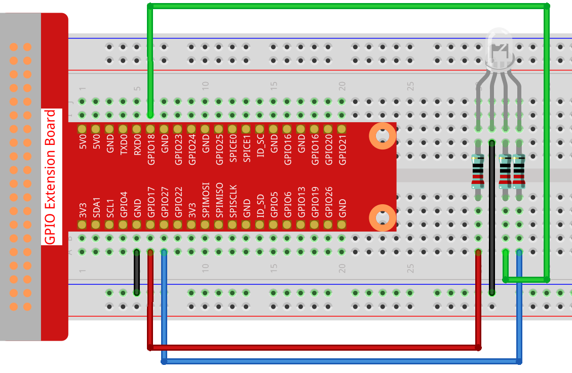
You should set up the breadboard as described in the project documentation or in the diagram below:
The WiringPi gpio utility can help with debugging if necessary. You already have this utility, you used it to verify the WiringPi installation in the Prerequisites section above.
The C code described in the Sunfounder RGB LED project uses software PWM. When run, the colors of the RGB LED change as expected. Varying voltages to the respective RGB pins using software PWM produces light of varying brightness (off to full bright) which will produce a wide range of colors.
Here is a slightly modified version of the Sunfounder C program that the controls an RGB LED:
Line 8 provides the command needed to build the program - gcc -o rgbled rgbled.c -lwiringPi -lpthread. The -l flags reference the libraries needed to build the program. -lwiringPi refers to the WiringPi library. It should be installed in the correct place along with WiringPi and the build command should just work. Libraries are usually located in /usr/lib. Line 9 provides the command to run the program.
Lines 18-20 specify, using the WiringPi pin numbering scheme, the GPIO pins 0, 1, and 2 for LedPinRed, LedPinGreen, and LedPinBlue respectively.
Line 24 contains the declaration of a signal handler for interrupt signals (SIGINT).
Lines 27-29 use the softPwmCreate() function to initialize the pins. The initial characters in the function name, softPwm, indicate that the pins are being initialized for software PWM. The function’s first parameter is the pin number. The second parameter is the starting pulse width. The final parameter is the range. See Pulse Width Modulation for Dummies, with a Slice of Raspberry Pi if you don’t understand these terms.
Lines 33-35, softPwmWrite() send the desired signal/voltage to the associated pin. The first parameter is the pin number, the same as in softPwmCreate() above. The second parameter is the pulse width. Notice that the pulse width was 0 in softPwmCreate(). This has the effect of setting the pin to zero volts. In softPwmWrite() the pulse width is set to the values specified by r_val, g_val, and b_val. These values represent the red, green, and blue values respectively. The maximum effective value for the pulse width is the range. This will result in full brightness/voltage. Any values greater than range will have no additional impact. It is important to note that the desired voltage will continue to flow to the pins until reset by another softPwmWrite().
The code snippet above is a continuation of the program. It shows the main() function. Lines 2–5 initialize the WiringPi library. The program exits if this initialization fails.
Line 7 specifies a signal handler to be called when SIGINT signal is received by the program. This is the signal set when the user enters ctl-C at the keyboard. This signal handler will terminate the program. This function was declared in the previous code snippet.
The calls to ledColorSet(...) within the while(keepRunning) loop at line 11 use hex numbers to set the colors. These are used to generate the full range of available colors. They must fall in the range of 0 to 0xff, recall the range value was specified in softPwmCreate(). I did change the values from the original Sunfounder code as the green LED used apparently has less resistance as it’s quite a bit brighter than the red and blue LEDs and therefore throws off the generated colors. Similarly, the blue LED seems to have more resistance as it is quite a bit dimmer than the other 2 LEDs. Changing the values, at least for my specific RGB LED, generated truer colors. The code loops, changing the LED color, until terminated via a ctl-C at the keyboard.
The code snippet above is a continuation of the previous code snippet. It contains the implementation of the interrupt handler described previously. It turns off all the RGB LED’s pins, resulting in the LED being completely off. pinMode() sets the mode for the specified pin (first parameter) to OUTPUT (second parameter). This changes the pin from a PWM pin to a pin that can only be set to ON or OFF. The voltage of an output pin cannot be varied. digitalWrite() sets the voltage for the specified pin to zero (LOW).
The program can be run, after compiling, using ./rgbled.
RGB LED in C (Hardware PWM)
Since the Sunfounder documentation doesn’t include a hardware PWM solution in C I decided to create one for myself. For this program modify the breadboard as shown below:
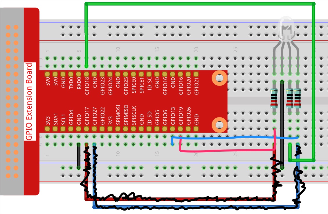
This time I’m using WiringPi pins 24, 1, and 23 for red, green, and blue, which correspond to BCM pins 19, 18, and 13 respectively. This is because these are 3 of the 4 hardware PWM pins on the Broadcomm BCM2835 board. Be sure to rewire the board to match these new pin assignments . The WiringPi gpio utility can help with debugging if necessary. You already have this utility, you used it to verify the WiringPi installation in the Prerequisites section above.
This version of RGB LED is very similar to the software PWM version above. There are 2 significant differences.
- Note the pin numbering used in lines 14-16. The WiringPi pin numbers used here correspond to the hardware PWM pins available on the GPIO board.
- The
ledInit()andledColorSet()functions (lines 30-48) are quite different. In these functions pin mode is set toPWM_OUTPUTvs. the use ofsoftPwmCreateandpwmWriteis used instead ofsoftPwmWrite. Line 34 sets the range. Note that the pin number isn’t specified for thepwmSetRange()call. There are 2 reasons for this. The first is that range is set at the channel level, not for individual pins. The second is that the WiringPi library doesn’t allow for the 2 channels to be specified separately. It sets both channels to the same value. Line 35,pwmSetClock(), (indirectly) sets the frequency. It specifies a divisor, in this case 2, that is used to divide the board’s oscillator’s clock frequency into the frequency used to control the pins. The divisor must be a number between 2 and 4095. As withpwmSetRange(),pwmSetClock()is specified at the channel level, not for individual pins. See Pulse Width Modulation for Dummies, with a Slice of Raspberry Pi for more discussion about clocks, frequency, and divisor as they relate to PWM.
The code snippet above contains the remainder of the program, main() and the interrupt handler. The interrupt handler is exactly the same as the interrupt handler in the software PWM version. Like the software PWM version of the program, the program loops until interrupted via a ctl-C.
The program is run using root privileges with sudo ./rgbledHardware. sudo is needed because direct hardware access is limited to users with root privileges. sudo provides root privileges to commands prefixed with sudo.
When running the program you’ll notice that the RGB LED doesn’t produce the expected colors. Sometimes it might show purple when it should be showing blue. Sometimes it might be turned off completely when it’s supposed to be showing a color. This behavior occurs because BCM pin 13 (blue) and BCM pin 19 (red) are on the same hardware channel. As explained above, when a signal is sent to one channel it will propagate to both pins that share that channel. Green, on BCM pin 12, is unaffected. One behavior I don’t understand is why sometimes the LED is off when it should be showing a color. This only happens for red (BCM19) and blue (BCM 13) pins. Perhaps the pins that share a channel don’t produce a signal at exactly the same time. Imagine a case where the blue pin is set to 0xff and the red pin is set to 0x00. If the red pin’s signal comes in slightly after the blue signal it would override the blue pin signal turning the LED off. The takeaway from all this is that for all intents and purposes, there are only 2 hardware PWM pins can be in use at the same time, and they can’t be on the same channel.
RGB LED in Go (Hardware PWM)
This version of RGB LED will work with the same breadboard setup as the C hardware PWM version. That is, it uses the hardware PWM pins on the GPIO board. Unlike the Sunfounder C version, and the first C version in this article, the Go library only supports hardware PWM. In my Pulse Width Modulation for Dummies, with a Slice of Raspberry Pi article I do include a software version of PWM in Go. It’s implemented in a companion program, freqtest.go in the runSoftwarePWM() function. Here is the code:
Lines 27-29 define the pins to use for the red, green and blue elements of the LED.
Lines 30-31 define default values to use for settings.
Lines 35–75 set the Mode to PWM and theDutyCycle for the LED’s pins. In DutyCycle(), the first parameter is the pulse width, called duty by go-rpio. The second parameter is the range, called cycle by go-rpio. The remainder of the lines contain comments and code that address the issues with trying to use 2 hardware PWM pins residing on the same channel as noted in the Hardware PWM in C section above.
This code snippet is a continuation of the program above. This gist shows ledInit(). It initializes the GPIO pins for use in the program. They set the mode (PWM), frequency, and duty cycle (providing parameters for pulse width and range (aka cycle)). As described in Pulse Width Modulation for Dummies, with a Slice of Raspberry Pi, the specified frequency must be between 4688 and 9,600,000.
This is part 3 of the program and shows the implementation of main(). Lines 2-4 initialize the go-rpio library. Line 5 makes sure the resources used are released when the program exits.
The remainder of the program prompts the user for the red, green, and blue values to use and the sets the pins approporiately.
The full program, rgbled.go, can be found in the gpio github repo.
Summary
That’s it, I hope you found this article interesting. To quickly review, this article covered the following:
- Setting up the physical environment needed to experiment with an RGB LED on a Raspberry Pi 3B+.
- Provided, via a link to another article3, the detailed knowledge of PWM that’s missing from the Sunfounder RGB LED Project.
- Provided and explained the C and Go code needed to set colors in an RGB LED using both hardware and software PWM.