Contents
Overview
This is the fourth article in a series that explores GPIO programming on a Raspberry Pi 3B+. It is a supplement to the Sunfounder LED Bar Graph project. You can find the full series here. The code for the series can be found in my gpio repository.
The Sunfounder LED Bar Graph project provides very good documentation regarding how to set up the project as well as describing the C code. This article is more geared towards describing what an LED bar graph is, what it’s good for, and how to control an LED bar graph using Go as well as C.
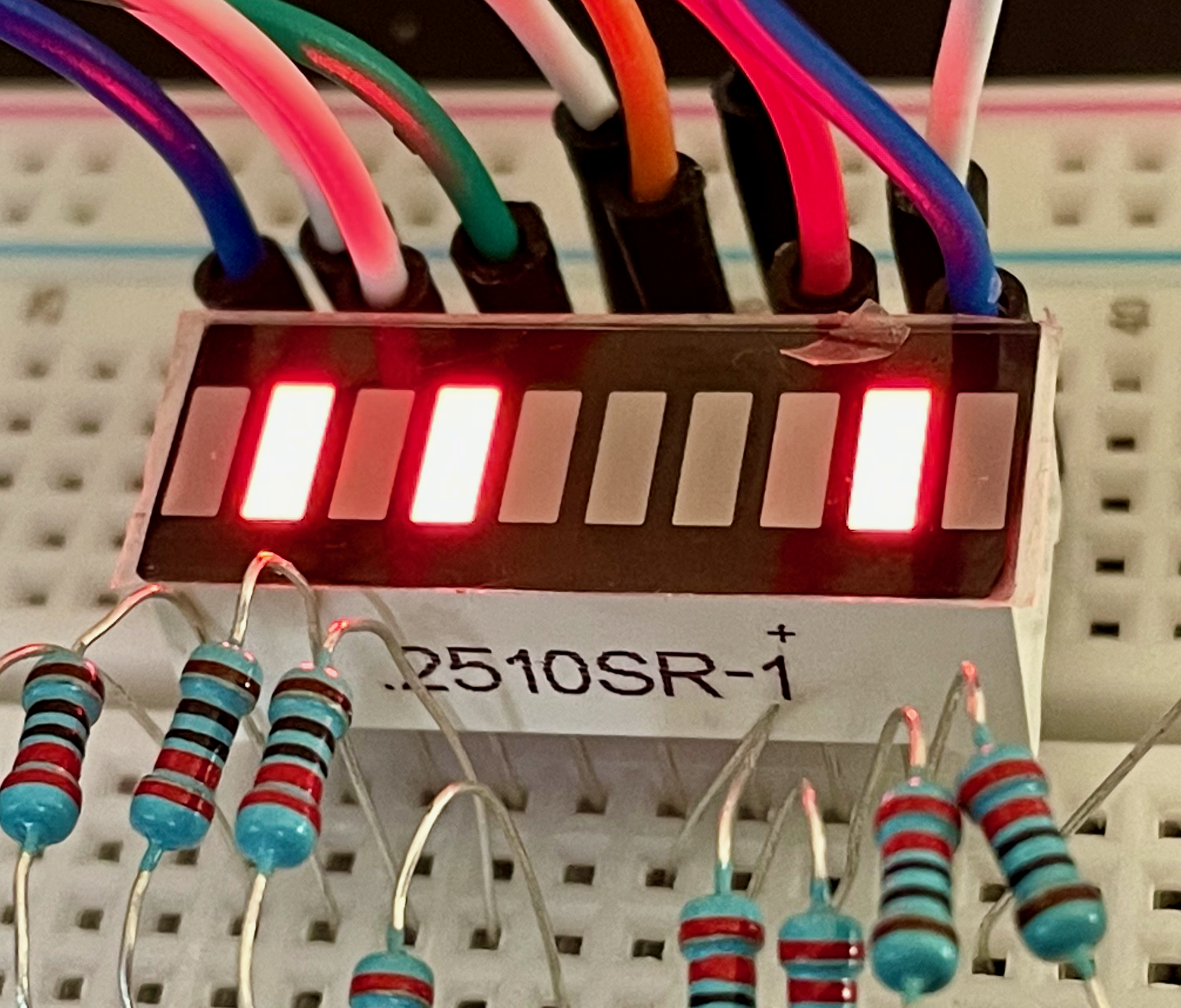
LED bar graphs consist of several LEDs embedded into a single component. In the picture below the bar graph contains 10 LEDs arranged side-by-side.
- Progress indicators
- Battery charge
- Voltmeter
- Sound meter
- Speed
In short, just about anything that requires an indication of a value at a relative position on a scale can be represented by an LED bar graph.
Prerequisites
This section is repeated in all articles in my Raspberry Pi GPIO series. If you’ve already completed a project from one of these articles you can skim this section for required items not included in other projects (e.g., an LED Bar Graph).
If you don’t have one, you’ll need a Raspberry Pi. I used a Raspberry Pi 3B+ with the ‘Stretch’ version of the Raspbian OS. The Raspberry Pi website has instructions on how to setup a new Raspberry Pi from scratch if you decide to go that way vs. buying a complete kit.
Other items you’ll need include:
- a breadboard (You may find this tutorial on breadboards helpful),
- some jumper wires,
- 10 220 Ohm resistors - this set actually has an assortment of resistors including 220 Ohm resistors.
- a 10 segment LED Bar Graph
- You should also consider getting a 40 pin female to female with a T-Type adapter to attach the GPIO outputs to the breadboard. You can use only jumper wires, but the T-Type adapter will make things easier and will help prevent damage to the GPIO pins on the Raspberry Pi. If you elect not to buy the 40 pin cable with T-Type adapter you’ll need to buy male-to-female jumper wires. Buying all these things separately will cost more than a kit however.
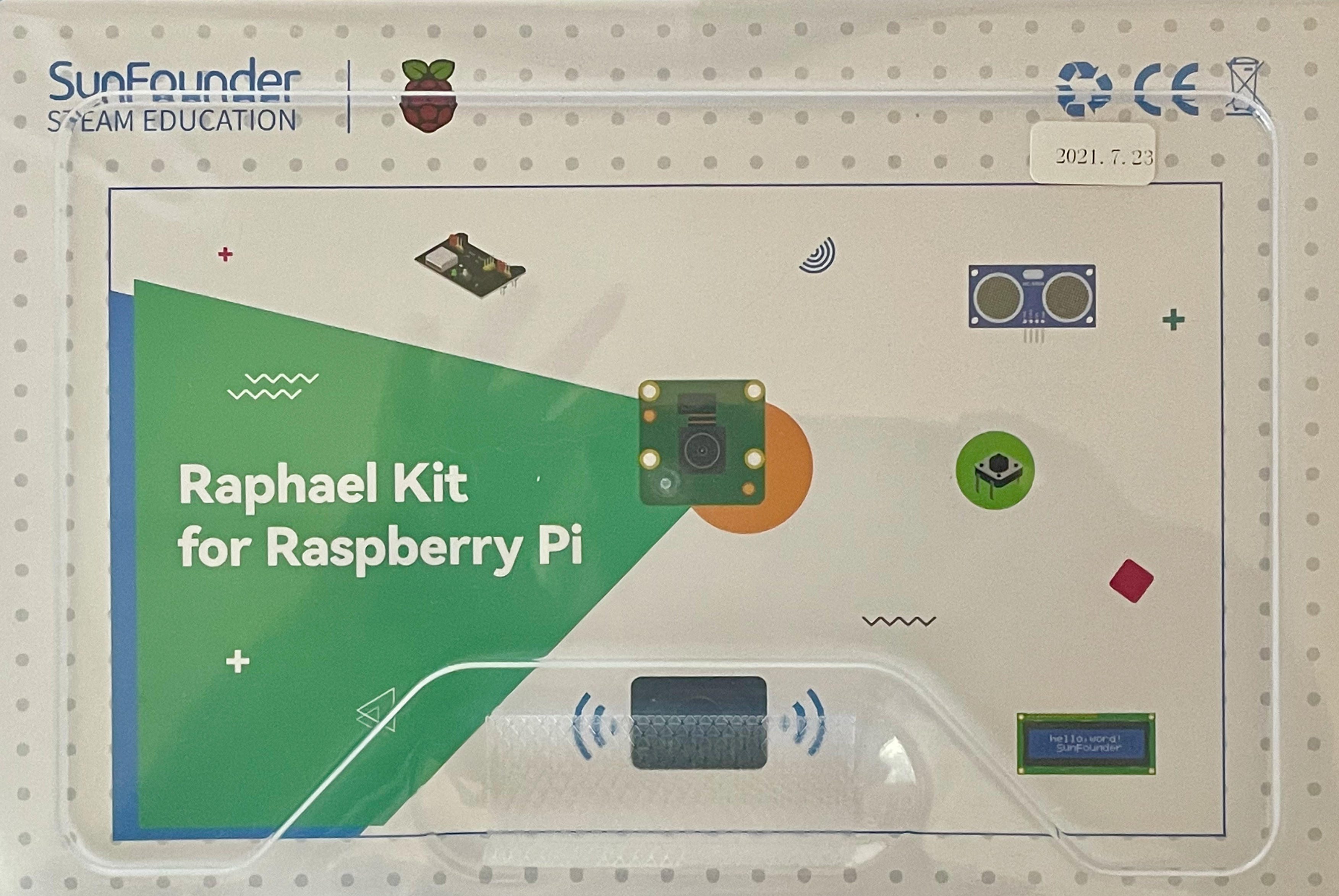
Here’s a simple kit that has all of the above. I’m finding the Sunfounder Raspberry Pi Ultimate Starter Kit especially useful. NOTE: The Ultimate Starter Kit and the Raphael Kit are the same product.
You will also need some basic C and Go programming knowledge as well as familiarity with logging on to a Raspberry Pi terminal, or into the desktop GUI that comes with some OS versions. Depending on the approach you take, you may need to connect a keyboard and monitor to the Raspberry Pi. I simply SSH into the Pi. You’ll also need familiarity with how to use an editor like vim or nano.
To compile and run the C program you’ll need the WiringPi library. It’s easy to get:
sudo apt-get install wiringpi
Then test the installation using:
pi@pi-node1:~/go/src/github.com/youngkin/gpio/rgbled $ gpio -v
gpio version: 2.50
Copyright (c) 2012-2018 Gordon Henderson
This is free software with ABSOLUTELY NO WARRANTY.
For details type: gpio -warranty

Raspberry Pi Details:
  Type: Pi 3B+, Revision: 03, Memory: 1024MB, Maker: Sony
  * Device tree is enabled.
  *--> Raspberry Pi 3 Model B Plus Rev 1.3
  * This Raspberry Pi supports user-level GPIO access.
In the above you’ll notice gpio version: 2.50. If you’re using a Rasberry Pi 4, use the instructions given in the Sunfounder Checking the WiringPi.
WiringPi is unique in that it includes a command line tool, gpio, as shown above, that can be used to manage, control, and query the GPIO board. This can be very handy. See the gpio reference for more information on what it can do and how to use it.
If you’re interested in Go development on a Raspberry Pi you’ll need to install the development environment onto the Raspberry Pi. Here’s a simple source that explains how to accomplish this. This source is a little dated, but the only significant issue is with the version of Go to install. The source shows installing Go 1.14.4.linux-arm64.tar.gz and 1.14.4.linuxarmv6l.tar.gz. The current versions are 1.17.1.linux-arm64.tar.gz and 1.17.1.linuxarmv6l.tar.gz. For the Raspberry Pi 3B+ the correct choice will be 1.17.1.linuxarmv6l.tar.gz. The other is intended for 64 bit systems like the Raspberry Pi 4 series. You can find current ARM versions of Go at the Golang download site.
For Go development you’ll also need the go-rpio library.
If you want to veer away from the cookbook style of the Sunfounder docs you’ll need some basic knowledge of Linux . For example, I won’t be explaining what root privileges are.
Setup and Code
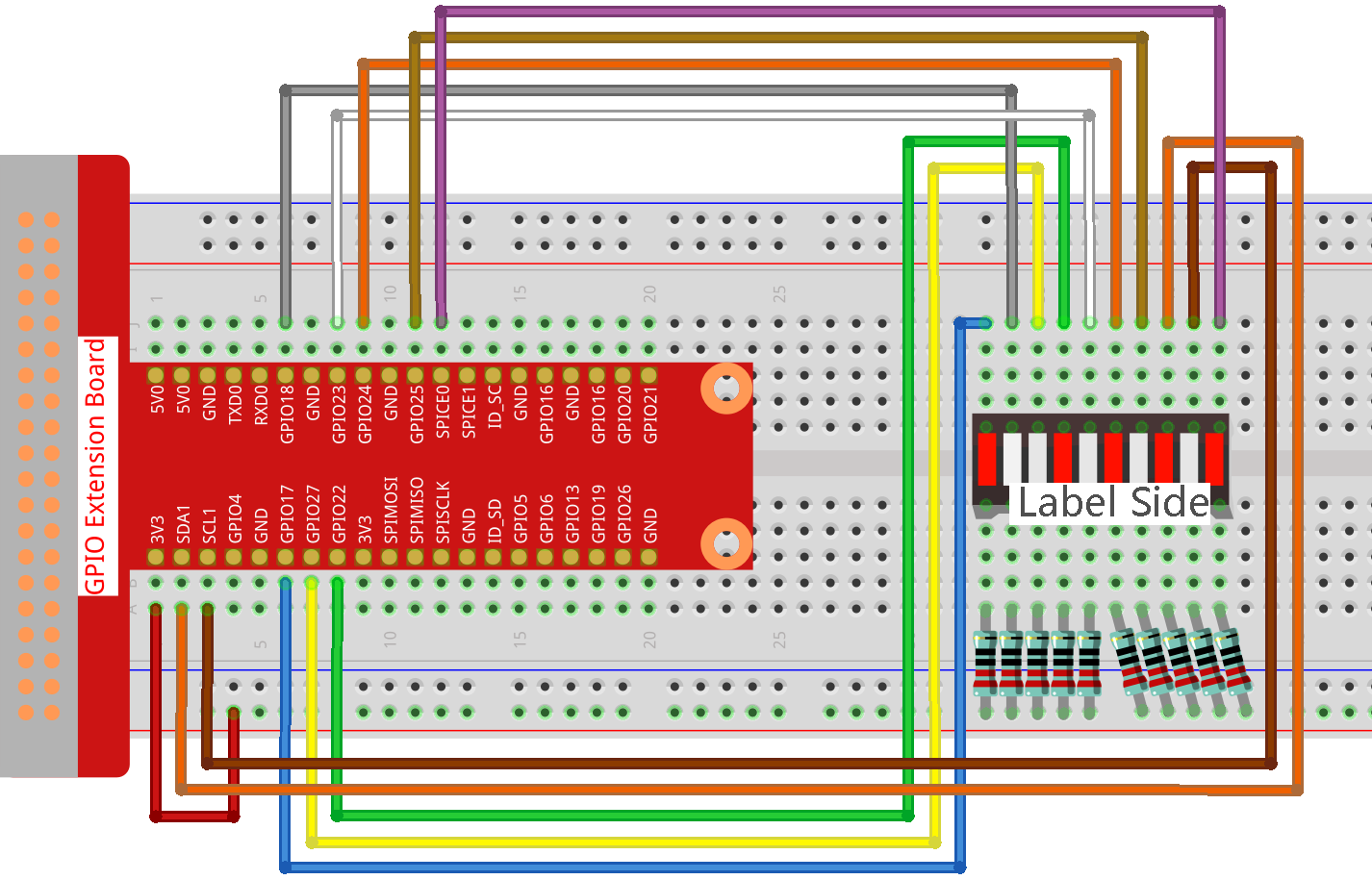
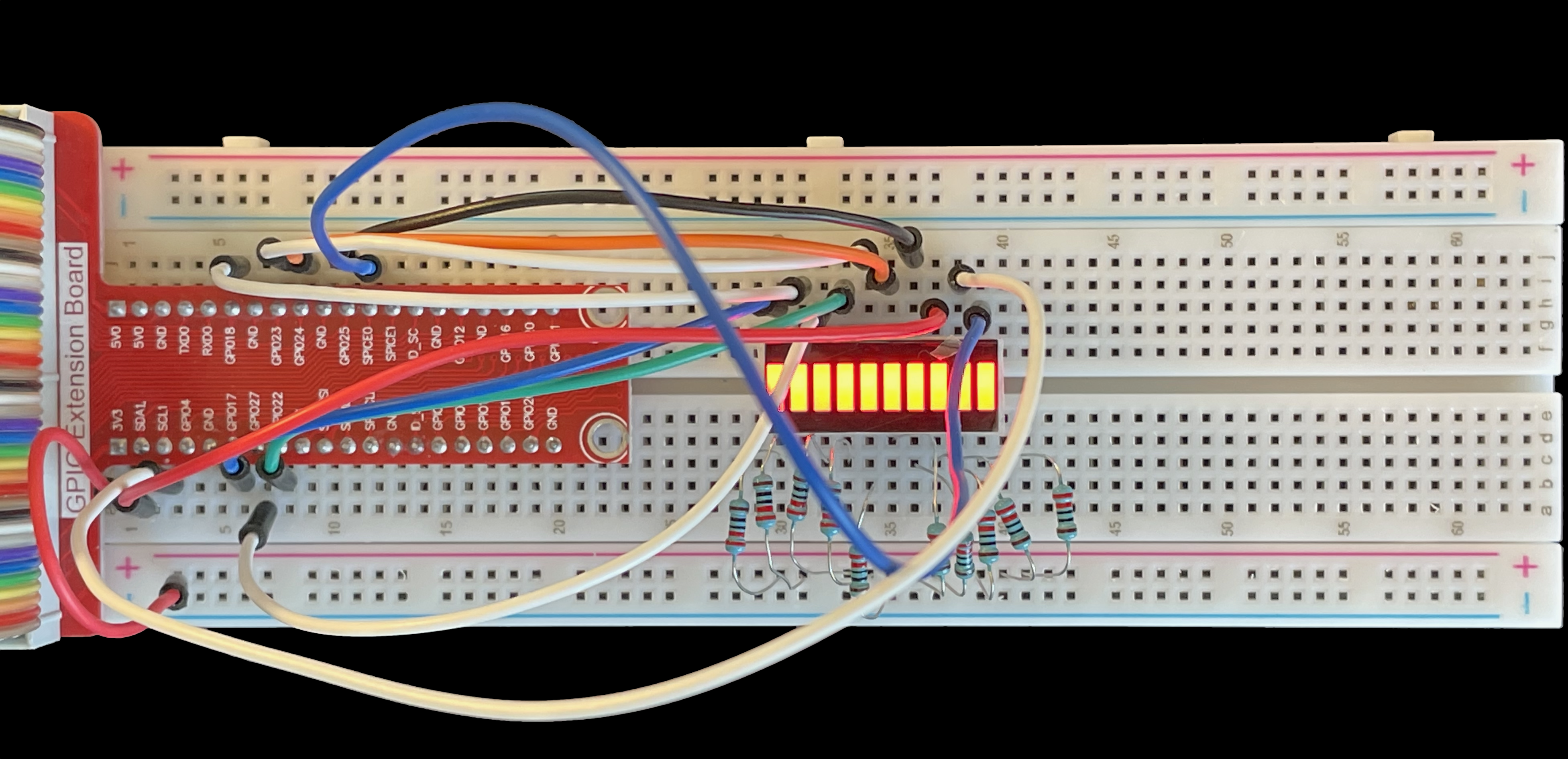
The breadboard should be wired as illustrated in the above diagram. If you’re unfamiliar with breadboards and breadboard diagrams this breadboard tutorial should be helpful.
One thing to note about the wiring diagram is that the resistors are all attached to the breadboard’s positive power bus on one side and the positive terminals of the LED bar graph on the other (Label Side). This means the LED bar graph is always getting power. In order for power to flow through a component one of the component’s terminals must be receiving power and the other must either not be receiving power or be connected to a negative or ground terminal. As noted, the resistors are directly attached to the power bus. In this diagram the GPIO pins are connected to the bar graph’s negative terminals. GPIO pins are set to either HIGH or LOW when in output mode (i.e., the pins are written to). HIGH means voltage is flowing to the pin, LOW means no voltage is flowing to the pin. Since completing a circuit requires one side of the circuit to have zero volts, and the bar graph is always receiving power via the power bus, the GPIO pins must be set to LOW voltage for current to flow and the LEDs to illuminate. In the code sections below, the LEDs are set to LOW when the LEDs should be illuminated.
LED Bar Graph in C
The code for this program can be found in the ledbargraph.c file in the github respository accompanying this series. It substantially similar to the Sunfounder program, but there are some important differences:
- This program includes an initialization function that turns all the LEDs on then off prior to continuing with the remainder of the program. This can be useful to verify that the LED bar graph is wired up correctly.
- This program includes an interrupt handler that cleans up when the program is interrupted via entering
ctl-Cat the terminal. The Sunfounder code does not. This cleanup includes resetting the bar graph to its state prior to the program starting, e.g., turning all the LEDs off. - Finally, this program also includes a function that randomly lights individual LEDs.
The major parts of the program are described in more detail below. The code is pretty well described in the Sunfounder article so I won’t repeat what’s already covered there.
Lines 9 & 10 show how to build and run the program. Line 19 declares the interrupt handler that’s used to intercept ctl-C input from the terminal. The rest of this section shows the init() function I added. It iterates through the pins array and first sets all the pins to LOW which has the effect of lighting them up. They’re set to LOW because the positive terminals of the LED bar graph are connected to the positive power bus. The pins are connected to the negative terminals of the bar graph. To get current to flow the pin states must be set to 0 volts, or LOW. The bar graph stays lit for 500 microseconds, then the LEDs are turned off, then there’s another delay of 500 microseconds before the program continues. The delays provide enough time to see the entire bar graph light up then turn off before the program continues. This provides a visual indication that the bar graph is connected properly.
This next section contains the functions that control the bar graph LEDs. The oddLedBarGraph(), evenLedBarGraph(), and allLedBarGraph() functions are taken directly from the Sunfounder code. I added the randomBarGraph() function on lines 1 - 12 just to make things more interesting. It uses the C standard library rand() function, line 5, to generate a random number that is adjusted on line 6 to be within the range of the pins array, offsets 0 through 9. That resulting number is used as the offset in the array to find the pin to be toggled (lines 7 and 9). There is a very brief delay between lighting the individual LEDs.
This last section of code shows the main() function and the interrupt handler, interruptHandler(). With the exception of the addition of lines 3, 18, and 19, main() is identical to the Sunfounder code. Line 3 registers the interruptHandler() function to receive the SIGINT signal associated with entering ctl-C at the terminal.
Lines 26 through 34 define the interruptHandler() function. It’s parameter, sig, contains the integer value of the signal being passed to the function. In our case it doesn’t matter what signal is passed, it’ll exit the program in any case.
Lines 27 thorugh 30 iterate through the pins array making sure each pin is set to OUTPUT mode, i.e., it can be written to, and setting it’s value to HIGH. Recall from above that setting the pin to LOW will light the pin, setting it to HIGH will turn it off.
Finally, the program exits on line 33 with a “success”, 0, exit code.
LED Bar Graph in Go
The code for this program can be found in the ledbargraph.go file in the github respository accompanying this series. This program in this section is very similar to its C counterpart above. There are some minor differences however. It doesn’t include functions to light the even and odd numbered LEDs. The major parts of the program are described in more detail below.
Line 6 provides the command to run the program. Lines 34 and 35, set up the slices that will contain the pin numbers and the associated go-rpio rpio.Pin instances. Line 33 shows the comparable WiringPi pin numbers as a cross-reference.
The Sunfounder GPIO Extension Board diagram doesn’t show the GPIO pins associated with SDA1, SCL1, and SPICE0 pins. The Raspberry Pi Pinout diagram does. Using this reference we can see that SDA1 maps to GPIO pin 2, SCL1 maps to GPIO pin 3, and SPICE0 maps to GPIO pin 8.
This next part of the program shows the init function. Lines 4 - 9 create rpio.Pin instances, define the pins as rpio.OUTPUT pins, and append them to the gpins slice defined in the first part of the program. Lines 10 - 13 set the pins to LOW state, lighting them up. Recall the discussion about the C program above that describes why the pins are set to LOW. Line 14 briefly pauses the program so the effect of lighting them up can be seen. Finally lines 15 - 17 turn the pins off by setting them to HIGH.
This part of the program contains the randBarGraph() and ledAll() functions. Line 3 seeds the Go random number generator which is used in line 9 to generate the pin number to be lit. Lines 5 - 15 and lines 22 - 30 contain Go select blocks which are used to make sure the 2 functions will exit if a ctl-C signal is received from the terminal. Specifically, line 6 and 23 receive the stop command via the stop channel and lines 7 & 24 exit the functions. The rest of the code is self-explanatory, the LEDs are turned on and off.
This final part of the program contains the main() and the signalHandler() functions. Lines 11 & 15 create unbuffered Go channels. The stop channel is used to signal other parts of the program that the program is exiting. This is needed because the signalHandler() is started in a separate goroutine on line 21. It must be able to stop the main goroutine before exiting the program. The stop channel is defined as taking an interface{} type. This means that the channel can contain any type. For this channel the type of the data sent isn’t important.
The sigs channel, defined on line 15, is used by the Go runtime to notify the signalHandler() that an interrupt signal has been received. signalHandler() is registered with the Go runtime on line 20. Line 21 starts the goroutine that will run signalHandler().
The rest of main() simply initializes the pins and runs the controlling functions.
LInes 28 - 42 contain the definition of signalHandler().
Summary
This brief article provided a quick overview of the LED bar graph component and its application in the real world. It also included some C code that wasn’t included in the original Sunfounder program. This additional code is used to show how to turn on the different LEDs in random fashion. Finally an implementation of this same C program was provided in Go. This was meant to demonstrate the usage of how use the go-rpio library implements functionality similar to WiringPi.
Hopefully you’ve learned enough from this article to use LED bar graphs in your own applications.
References
- Sunfounder LED Bar Graph project
- Sunfounder GPIO Extension Board diagram
- Raspberry Pi Pinout diagram
- WiringPi library for C
- WiringPi website
- go-rpio library for Go
- Other articles in my Raspberry Pi GPIO series
- The gpio repository containing the code for this article
- How to setup a new Raspberry Pi from scratch
- How to use a breadboard